Ardupilot Control of R/C Sailplane
Jack Quindlen
[jfq5000@gmail.com]
Department of Aerospace Engineering
The goal of this project is to create an Arduino-based fly-by-wire RC system
for an Omega 2 2-meter sailplane. This
glider is being used for autonomous soaring research and needs a complex
open-source autopilot to test energy harvesting techniques using thermal,
ridge, and dynamic soaring. The
Arduino-based system forms a good template for an autopilot, especially when
using an Arduino Mega Ardupilot. Before building a complex system, the first
step to implementing such an autopilot is to use the Ardupilot as a flight
control computer for a R/C aircraft.
The direct reason for working with the Omega 2 airframe is to test out a flush air data sensor designed in the AVIA lab for measuring wind axes. This sensor will be used to validate airspeed control methods utilizing angle of attack instead of pitch angle. The autopilot and the novel sensor system places additional requirements on the flight control system that are not required from a traditional R/C setup. These aspects include:
· Wireless data transmission to send telemetry data to a ground station
· GPS and possible pressure altitude sensor for wind sensor verification
· Onboard flap crow, V-tail, and aileron mixing
· Autopilot commands in addition to user R/C commands
The sailplane's airframe itself will also have to be slightly modified to incorporate a hi-start launcher as a means of launching the aircraft into the sky. A CG hook will have to be added to a reinforced section of the aircraft's belly for the bungee strap of the hi-start.
___________________________________________________________________________
R/C Setup
The radio control system uses an 8 channel 72 MHz transmitter with a hacked
receiver for PPM signals. The receiver
used is a Castle
Creations Berg 4 with a R32 radio crystal.
The 72 MHz radio frequency for the radio was chosen over a 2.4 GHz
system because the XBee, discussed in another section, already uses the 2.4 GHz
spectrum. Also, the hacked Berg receiver
allows 8 PPM channels to pass through only one of the receiver's channels,
allowing a large number of input channels for a cheap R/C receiver.

V-tail control description. Source: RCgroups.com
RADIO INPUTS
The 8 channels read into the R/C system include control surface commands as well as additional signals intended for later use in the autopilot. In order, the 8 input channels in the receiver are:
1. Right aileron
2. Left aileron
3. Elevator
4. Rudder
5. Autopilot mode
6. Pitch trim tab
7. Autopilot airspeed command
8. Flap setting
Where channels 5 and 7 are intended for later use in a longitudinal autopilot. The elevator and rudder input channels do not map directly to a control surface since they have to be mixed to match the aircraft's V-tail.
SERVO OUTPUTS
The Ardupilot has 6 servo outputs for the control surfaces. In order, these 6 outputs are:
1. Right aileron
2. Right flap
3. Left flap
4. Left aileron
5. Left ruddervator
6. Right ruddervator
All the surfaces are calibrated for 1 inch of movement in either direction, with the exception of the flaps, which are calibrated for 2 inches of movement when fully deployed. These deflections are slightly extreme, but can be limited later if necessary.
MIXING
Usually, computer radio transmitters would handle the control surface mixing, but since the Ardupilot will later be used for an autonomous autopilot, any necessary mixing had to be implemented onboard the Ardupilot .
1. V-tail mixing
The most obvious control mixing required is V-tail mixing. The Omega 2 is a V-tail glider with 2 ruddervators in place of a traditional elevator and rudder setup. The mixing takes the elevator and rudder input channel commands and translates them into the appropriate left and right ruddervator signals. The mixing also includes the pitch trim setting to adjust the longitudinal control of the aircraft.
2. Flap crow mixing
For landing, the pilot will use flap crow mixing to lower the flaps down and simultaneously raise the ailerons up to slow the aircraft. The flap setting input command controls the amount of flap and aileron movement. The flap deflections are set for 0°, 20°, or 40° trailing edge down with corresponding aileron deflections of 0°, 10°, and 20° trailing edge up. Additionally, the ruddervators are coupled with the flap setting so that there will be a 0°, 10°, or 20° nose down deflection automatically added to the servo output to adjust for the sudden increase in nose up pitching moment due to the flap deflection.
3. Differential ailerons
The last type of mixing used is differential ailerons to
reduce the adverse yaw from aileron deflections. For differential ailerons, the upward moving
aileron moves more than the downward moving aileron. In this case, the up aileron moves 2° for
every 1° the down aileron deflects. This
ratio was taken from the Great Planes Spirit Elite 2-Meter Sailplane manual, a
similarly sized high performance glider.
___________________________________________________________________________
Sensor/Wireless Integration
The primary reason for implementing the R/C system and the eventual autopilot
is to test and verify a wind axes sensor for controlling aerodynamic angles of
attack and sideslip. This wind axes
sensor uses a custom-built nosecone with 5 pressure ports along with 2 static
pressure ports on the sides. Three MPXV-7002
differential pressure sensors are used to measure the difference in
pressure along the sides of the nosecone.
One sensor connects the center port of total pressure with a T-junction
of the 2 static pressure ports to obtain airspeed. The other 2 differential pressure sensors are
connected to the remaining 4 ports to obtain the angles of attack and
sideslip.
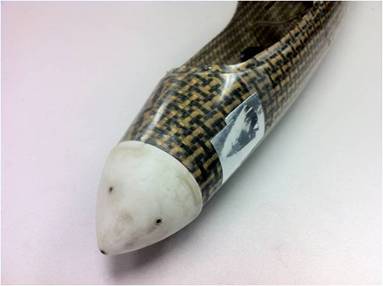
Nosecone with pressure ports.
GPS measurements are taken for position monitoring and for verifying the wind axes measurements. The GPS receiver used for the aircraft is a MediaTek MT3329 unit with a built-in breakout board specifically configured for the Ardupilot Mega. The GPS connection was set to 38400 baud rate. Even though the GPS unit cannot measure airspeed or the aerodynamic angles, the groundspeed measurements give a good indication of the ballpark range expected for the wind sensor. The groundspeed can be combined with the change in altitude measurements to give the pitch angle of the aircraft, which allows for a comparison of angle of attack or pitch angle airspeed control methods. If the altitude measurements from the GPS unit prove too noisy, the GPS can be coupled with a pressure sensor to determine change in altitude more accurately.
Wireless data transmission is handled with 2.4 GHz XBee Pro modules. Possible interference with the data transmission is the reason a 2.4 GHz radio system was not chosen for the R/C radio transmitter and receiver. The XBee modules were set to 57600 baud rate to allow for large data packets to pass quickly to the ground station so no information is lost or bottled necked, while the messages themselves were also kept very terse to save bits. All messages also include the Arduino time message to give a quick way of error checking and staggering the messages. The message formats are listed below:
1. GPS packet:
[Identifier; Arduino timer; latitude; longitude; altitude;
groundspeed; course; # of SVs visible; GPS time]
example: [$GP; 1101; 23.0985721;
120.2843832;
120; 20; 123.1; 4; 03:35:23.10]
Note: all units in meters, meters/second, seconds, or degrees where appropriate.
2. Wind sensor packet:
[Identifier; Arduino timer; airspeed; angle of attack; angle
of sideslip; checksum]
example: [$PR; 1102; 512, 512, 512, 7221];
For right now, all the data processing is handled off-line so the raw digital data sent over the XBee rather than a transmitted form. The checksum is the sum of 3*airspeed + 5*angle of attack + 7*angle of sideslip. Eventually, a Neural Network trained function will be added to the Arduino code so that the XBee will transmit the airspeed and aerodynamic angles directly rather than the digital values.
There are also 2 debugging statements for sending the radio inputs and servo outputs back to the ground station.
3. Radio Inputs:
[Identifier; Arduino timer; L. aileron; R. aileron;
elevator; rudder; autopilot mode; pitch trim; autopilot airspeed; flap setting]
example: [$RI; 1103; 1500; 1500; 1600; 1400; 2000; 1507; 1837; 1900]
4. Servo outputs:
[Identifier; Arduino timer; L. aileron; L. flap; R. flap; R.
aileron; L. ruddervator; R. ruddervator]
example: [$SO; 1104; 1500; 1500; 1500; 1500; 1600; 1200]
In order to connect all these sensors and various radios, a proto-board shield was created to fit on top of the Ardupilot Mega board. This shield was necessary to save precious space in the extremely cramped aircraft fuselage. There is not much usable space within the front of the aircraft due to structural reinforcements and mounting brackets, so placing the proto-board on top of the Arduino reduced the amount of wiring needed and kept everything tightly packed. The board included pins for the 3 differential pressure transducers, which were also fixed to the top of the board. The XBee data in/out pins were also attached the front of the board for ease of connection and the GPS connector was kept clear so nothing would have to be changed there.
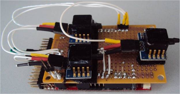
Proto-board shield with 3 differential pressure transducers.
___________________________________________________________________________
Airframe
Before assembling the aircraft, the sailplane first had to be modified with a CG hook for hi-start launching. A hi-start launcher consists of a giant bungee launcher to slingshot an unpowered glider high into the air. Since this modified Omega 2 has no motor, this method is necessary for long endurance flights. This method also puts stress on the fuselage, especially in the area where the hook is located, so the basic Omega 2 fuselage has to be reinforced to deal with the stresses. The CG hook is placed 1/2 inch ahead of the CG location, or 2.25 inches behind the wing's leading edge. The bottom of this area is reinforced by a 2 inch thick balsa block sanded to the fuselage's bottom shape with a 1/8 inch thick plywood plate on top of it. This plywood board is epoxied to the sides of the fuselage as well to form a firm connection. A 4-40 threaded rod was then drilled in and bent to make a hook out of the bottom of the aircraft.
ASSEMBLY
After attaching the CG hook, a 1/8 inch thick balsa board was cut to cover up a 9 inch section of the inside of the fuselage as a mounting board for all the electrical components. It was screwed into 2 pre-existing 4-40 nuts on the aircraft's inside so that it could also be quickly removed while still covering the CG hook and its reinforcements.

Inside platform without electronics.
An 11.1 V 2100 mAh Lithium Polymer battery was used to power the system. This was the same battery used before on the aircraft when it had a motor. Previously, this heavy motor sat in the front of the aircraft and dominated the CG location. With this motor gone, the 11.1 V battery, which previously sat on the CG, can be moved up to the nose to make up for the loss of weight at the front of the aircraft. It also provides more than enough power so longer flight times can be achieved.

Battery compartment along with tygon tubing.
Since the components all run at 5 volts rather than 11.1 V, a voltage divider is used between the battery and the rest of the components. This system was manufactured by a previous student and consists of 2 active LM394 dividers for stepping to 5V and 2 inactive LM1084 dividers for 5V to 3.3V that had been disconnected. These 2 active dividers are attached to the XBee itself and also to the Ardupilot Mega, which powers the rest of the system and servos.
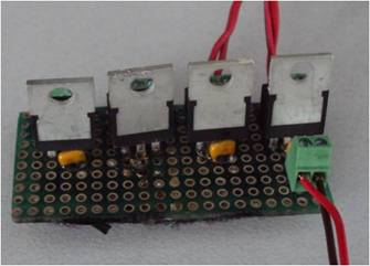
Voltage divider.
All the electronics components are then spread out throughout the aircraft in various locations. The radio receiver is placed in the tailboom with the antenna running out the tail. This keeps it out of the way of the other two antennas and it's slim enough to fit in this tight area. The receiver and the servos are plugged directly into the servo rail of the Ardupilot Mega and follow the same numbering scheme listed in the radio section. The receiver is connected to Input Signal Pin 1 and a jumper is placed between Input Signal Pins 2 and 3. This turns the Ardupilot into PPM mode. Lastly, the pressure transducers are connected to the nosecone ports via 3/32 inch inner diameter tygon tubing.
The GPS and XBee are placed on the canopy of the aircraft so the antennas will have good reception. The Omega 2 is a carbon fiber aircraft, so the antennas must clearly protrude from the aircraft or else they will be trapped within the fuselage. To avoid this, the XBee is attached to the inside of the canopy with the antenna sticking out of an access hole. This same hole is used for the GPS unit, which is directly mounted onto the external side of the cockpit. Since the MediaTek unit does not have an external antenna, this had to be done or else there was a high rate of signal dropout.
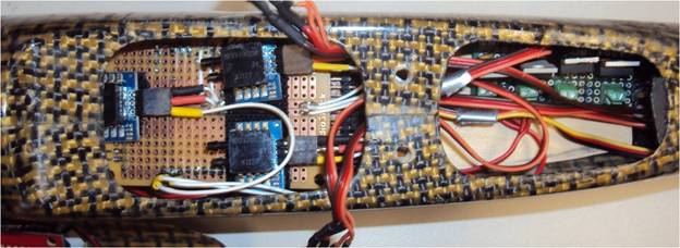
Electronics compartment

GPS mounted on top of canopy. XBee antenna visible right behind the GPS unit.
___________________________________________________________________________
Results
The sailplane was test flown under R/C control for two short hand launch flights. These demonstrated that the aircraft works as intended, but further tests and tweak will have to be performed before the aircraft is ready for hi-start launching.

Finished Omega 2.
One issue identified with the test flights is power dissipation within the voltage divider. When all the servos are moving, the voltage divider becomes very hot and causes the power to drop. This slows and eventually stops the servos, completely unacceptable in flight. To get around this problem, the flights were performed with no flaps. Before hi-starting the aircraft, new voltage dividers will have to be included or a better way of powering the servos.
Another problem is with the XBee and GPS antenna placement. Because of the carbon fiber fuselage, these had to be placed clear of the fuselage. The XBee antenna is fairly well placed, but the entire GPS unit had be placed outside the canopy. This cannot be used for hi-start flights because the forces from the launch could very well dislodge and lose the GPS unit. An antenna will have to be acquired for this GPS unit or a different unit with a built-in external antenna will have to be used.
Lastly, there are a number of small additions to the Ardupilot or airframe that will have to addressed before the aircraft is fully capable. The aluminum rod bent too easily and will have to replaced with a stronger rod. The Neural Network functions for the airspeed and aerodynamic angles will have to added to the Arduino code so that the Ardupilot can use the measurements in the autopilot. The proto-board is also a good prototype, but a more professional PCB board should be sent to a company for etching before using it on full flight tests.
___________________________________________________________________________
Arduino Code
Main Function
//Jack Quindlen
//ME 597D Final Project
//Main Ardupilot Function
//5/2/2012
//This is the file that executes the R/C autopilot controller.
//Flaps are disabled in this verison for
simplicity
//Autopilot is not enabled in this version
////////////////////
//////Includes//////
#include <FastSerial.h>
#include <AP_Common.h>
#include <Arduino_Mega_ISR_Registry.h>
#include <APM_RC.h> // ArduPilot
Mega RC Library
#include <AP_GPS.h>
#include <AP_Math.h>
FastSerialPort0(Serial); //Serial connection
FastSerialPort1(Serial1); //GPS
FastSerialPort3(Serial3); //XBee
Arduino_Mega_ISR_Registry isr_registry;
APM_RC_APM1 APM_RC;
AP_GPS_NMEA NMEA_gps(&Serial1);
GPS *gps
= &NMEA_gps;
#define T6 1000000
#define T7 10000000
const uint8_t sirf_to_nmea[] = { 0xa0, 0xa2, //
preamble
0x00,
0x18, // message length
0x81,
0x02, // switch to NMEA
0x01,
0x01, // GGA on with checksum
0x01,
0x01, // GLL on
0x01,
0x01, // GSA on
0x01,
0x01, // GSV on
0x01,
0x01, // RMC on with checksum
0x01,
0x01, // VTG on with checksum
0x01,
0x01, // MSS on
0x01,
0x01, // EPE on
0x01,
0x01, // ZPA om
0x00,
0x00, // pad
0x96,
0x00, // 38400
0x01,
0x25, // checksum TBD
0xb0,
0xb3
}; // postamble
////////////////
/////////////////
////Variables////
////////////////////////
////Define RC Inputs////
//Aileron inputs (should be the same)
const int ail_1_input_chan = 0; //Channel #1
const int ail_2_input_chan = 1; //Channel #2
int ail_1_input; //Input value
int ail_2_input; //Input value
//Elevator input signal
const int elevator_input_chan
= 2; //Channel #3
int elevator_input; //Input
value
//Rudder input signal
const int rudder_input_chan
= 3; //Channel #4
int rudder_input; //Input
value
//Autopilot toggle switch input
const int autopilot_input_chan
= 4; //Channel #5
int autopilot_input;
//Input value
//Pitch trim input signal
const int pitch_trim_input_chan
= 5; //Channel #6
int pitch_trim_input;
//Input value
//Airspeed slider input
const int airspeed_input_chan
= 6; //Channel #7
int airspeed_input; //Input
value;
//Flap 3 way switch
const int flap_input_chan =
7; //Channel #8
int flap_input; //Input
value;
/////////////////////////
////Define RC Outputs////
//Left aileron
const int left_ail_chan =
CH_1; //Predefined Channel #1
int left_ail = 1500; //PWM
signal
//Left flap
const int left_flap_chan =
CH_2; //Predefined Channel #2
int left_flap = 1500; //PWM
signal
//Right flap
const int right_flap_chan =
CH_4; //Predefined Channel #4
int right_flap = 1500;
//PWM signal
//Right aileron
const int right_ail_chan =
CH_3; //Predefined Channel #5
int right_ail = 1500; //PWM
signal
//Left ruddervator
const int left_ruddervator_chan
= CH_5; //Predefined Channel #6
int left_ruddervator =
1500; //PWM signal
//Right ruddervator
const int right_ruddervator_chan
= CH_7; //Predefined Channel #7
int right_ruddervator =
1500; //PWM signal
//Crow mixes
int ail_crow = 0;
int pitch_crow = 0;
///////////////////////
////Pressure Sensor////
int val10 = 0;
//Analog Pin 10 (airspeed)
int val12 = 0;
//Analog Pin 12 (alpha)
int val14 = 0;
//Analog Pin 14 (beta)
int check = 0;
//Checksum
//Timer
int ardu_time = 0;
void setup()
{
Serial.begin(38400);
//Serial port
//////////////////////
////GPS connection////
Serial1.begin(38400);
for (uint8_t i
= 0; i < sizeof(sirf_to_nmea); i++)
Serial1.write(sirf_to_nmea[i]);
gps->init();
/////////////////////////////////////
////PPM radio receiver
connection////
isr_registry.init();
APM_RC.Init(&isr_registry); // APM Radio initialization
APM_RC.enable_out(left_ail_chan); //Left aileron
APM_RC.enable_out(right_ail_chan); //Right aileron
APM_RC.enable_out(left_ruddervator_chan); //Left ruddervator
APM_RC.enable_out(right_ruddervator_chan); //Right ruddervator
//APM_RC.enable_out(left_flap_chan); //Left flap
//APM_RC.enable_out(right_flap_chan); //Right flap
///////////////////////
////XBEE connection////
Serial3.begin(57600);
delay(1000); //Pause 1 second
}
void loop()
{
/////////////////////////
////RC inputs/outputs////
if (APM_RC.GetState()
== 1)
{
readInputPacket();
//Read in radio input
flap_output(flap_input); //Flap servo commands
aileron_output(ail_1_input,
ail_2_input); //Aileron servo commands
vtail_output(elevator_input, rudder_input, pitch_trim_input); //Ruddervator
servo commands
sendServoCommands();
//Write servo commands
//Send them back over serial for
debugging
//serialInputPacket();
//Send radio input over serial
//serialOutputPacket();
//Send servo commands over serial
}
////////////////
////GPS data////
gps->update();
sendServoCommands();
//Write servo commands
if (gps->new_data) {
if (gps->fix)
{ //Got a fix
sendServoCommands();
//Write servo commands
serialGPSpacket();
//Send GPS packet over serial
}
else { //Didn't get a fix
ardu_time
= millis();
Serial3.print("$GF;");
Serial3.print(ardu_time);
Serial3.println(" No
fix");
}
gps->new_data = false;
}
////////////////////////
////Wind sensor data////
GetAnalogData();
//Read pressure transducers
serialWindPacket();
//Send wind sensor data packet over serial
}
Radio Functions
//Jack Quindlen
//ME 597D Final Project
//5/2/2012
/////////////////////////////////////////////
//Radio and servo functions for R/C control//
/////////////////////////////////////////////
/////////////////////////////////
////Read radio input channels////
void readInputPacket()
{
ail_1_input = APM_RC.InputCh(ail_1_input_chan);
//Left aileron
ail_2_input = APM_RC.InputCh(ail_2_input_chan);
//Right aileron
elevator_input
= APM_RC.InputCh(elevator_input_chan);
//Elevator command
rudder_input
= APM_RC.InputCh(rudder_input_chan);
//Rudder command
autopilot_input
= APM_RC.InputCh(autopilot_input_chan);
//Enable/disable autopilot
pitch_trim_input
= APM_RC.InputCh(pitch_trim_input_chan);
//Pitch trim adjustment
airspeed_input
= APM_RC.InputCh(airspeed_input_chan);
//Autopilot airspeed command
flap_input = APM_RC.InputCh(flap_input_chan);
//Flap setting
}
////////////////////////////////
////Write commands to servos////
void sendServoCommands()
{
APM_RC.OutputCh(left_ail_chan, left_ail); //Left
aileron
//APM_RC.OutputCh(left_flap_chan, left_flap);
//Left flap
//APM_RC.OutputCh(right_flap_chan, right_flap);
//Right flap
APM_RC.OutputCh(right_ail_chan, right_ail);
//Right aileron
APM_RC.OutputCh(left_ruddervator_chan, left_ruddervator);
//Left ruddervator
APM_RC.OutputCh(right_ruddervator_chan, right_ruddervator);
//Right ruddervator
}
//////////////////////////////
////Servo output functions////
//Aileron commands
void aileron_output (int
aileron_1, int aileron_2)
{
int neutral =
1500; //Flaps neutral position
left_ail =
aileron_1;
right_ail =
aileron_2;
//Differential Ailerons: 2 deg UP to 1
deg DOWN
//Left aileron
if (left_ail
< (neutral-50))
{
left_ail =
(neutral-left_ail)/2;
left_ail =
neutral-left_ail;
}
//Right aileron
if (right_ail
> (neutral+50))
{
right_ail =
(right_ail - neutral)/2;
right_ail =
right_ail + neutral;
}
//Add flap crow mixing
left_ail = left_ail + ail_crow;
right_ail = right_ail - ail_crow;
}
//Vtail mixing
//Ruddervators combine elevator and rudder
commands
void vtail_output (int
elevator, int rudder, int
trim)
{
int neutral =
1500;
int max_rv = 2100;
int min_rv = 900;
int change =
300;
elevator = elevator - neutral;
elevator = constrain(elevator,-change,change);
rudder = rudder - neutral;
rudder = constrain(rudder,-change,change);
trim = trim - neutral;
left_ruddervator
= neutral + elevator + rudder + trim + pitch_crow;
right_ruddervator
= neutral - elevator + rudder - trim - pitch_crow;
left_ruddervator
= constrain(left_ruddervator,min_rv,max_rv);
right_ruddervator
= constrain(right_ruddervator,min_rv,max_rv);
}
//Flap settings
void flap_output (int
flap)
{
int neutral =
1900; //
int flap_trim = 250; //Hard-coded flap zeroing adjustment
left_flap =
neutral - ((neutral - flap)/2) + flap_trim; //Right
flap command
right_flap =
((flap - neutral)/2) + (3003- neutral) - flap_trim;
//Left flap uses opposite command
//Perform crow mixing when flaps
deployed
if (flap < 1650 & flap >
1350) //Half flaps
{
ail_crow =
125; //10 degrees ailerons up
pitch_crow
= 100; //10 degrees elevator down
}
else if (flap <= 1350) //Full
flaps
{
ail_crow =
250; //20 degrees ailerons up
pitch_crow
= 200; //20 degrees elevator down
}
else //No flaps
{
ail_crow =
0; //No crow mixing
pitch_crow
= 0; //No crow mixing
}
}
Sensor Functions
//Jack Quindlen
//ME 597D Final Project
//5/2/2012
////////////////////////////////////////////////////////
//Read pressure transducers for wind axes measurements//
////////////////////////////////////////////////////////
void GetAnalogData()
{
val10 = analogRead(10); //Read analog input (airspeed)
val12 = analogRead(12); //Read analog input (alpha)
val14 = analogRead(14); //Read analog input (beta)
check =
((3*val10)+(5*val12)+(7*val14)); //Calculate checksum
}
Serial Functions
//Jack Quindlen
//ME 597D Final Project
//5/2/2012
///////////////////////////////////////
//Serial outputs to be send over XBee//
///////////////////////////////////////
////////////////////////////////////
////Repeat back the radio inputs////
void serialInputPacket()
{
ardu_time = millis();
Serial3.print("%RI;");
//Identifier
Serial3.print(ardu_time);
//Timer
Serial3.print(";");
Serial3.print(ail_1_input);
Serial3.print(";");
Serial3.print(ail_2_input);
Serial3.print(";");
Serial3.print(elevator_input);
Serial3.print(";");
Serial3.print(rudder_input);
Serial3.print(";");
Serial3.print(autopilot_input);
Serial3.print(";");
Serial3.print(pitch_trim_input);
Serial3.print(";");
Serial3.print(airspeed_input);
Serial3.print(";");
Serial3.println(flap_input);
}
///////////////////////////////////////
////Send back the servo PWM signals////
void serialOutputPacket()
{
ardu_time = millis();
Serial3.print("$SO;");
//Identifier
Serial3.print(ardu_time);
//Timer
Serial3.print(";");
Serial3.print(left_ail);
Serial3.print(";");
Serial3.print(left_flap);
Serial3.print(";");
Serial3.print(right_flap);
Serial3.print(";");
Serial3.print(right_ail);
Serial3.print(";");
Serial3.print(left_ruddervator);
Serial3.print(";");
Serial3.println(right_ruddervator);
}
/////////////////////////////
////Send GPS measurements////
void serialGPSpacket()
{
ardu_time = millis();
Serial3.print("$GP;");
//Identifier
Serial3.print(ardu_time);
//Timer
Serial3.print(";");
Serial3.print((float)gps->latitude / T7); //degrees
Serial3.print(";");
Serial3.print((float)gps->longitude / T7); //degrees
Serial3.print(";");
Serial3.print((float)gps->altitude / 100.0); //meters
Serial3.print(";");
Serial3.print((float)gps->ground_speed / 100.0);
//meter/second
Serial3.print(";");
Serial3.print((int)gps->ground_course / 100);
//degrees
Serial3.print(";");
Serial3.print(gps->num_sats); //Number of satellites visible
Serial3.print(";");
Serial3.println(gps->time);
//UTC time
}
/////////////////////////////////////
////Send wind sensor measurements////
void serialWindPacket()
{
ardu_time = millis();
Serial3.print("$PR;");
//Identifier
Serial3.print(ardu_time);
//Timer
Serial3.print(";");
Serial3.print(val10); //Airspeed
Serial3.print(";");
Serial3.print(val12); //Angle of
attack
Serial3.print(";");
Serial3.print(val14); //Angle of
sideslip
Serial3.print(";");
Serial3.println(check);
//Checksum
}