 | ||||||
 | ||||||
|
|
| Introduction | |||||||||||||||||
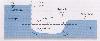
A hydraulic jump is a sudden dissipation of energy caused by a change from super-critical to sub-critical flow. The concept is very similar to sudden expansion in pipe flow, except that hydraulic jumps occur in open-channel flow. At the start of the jump, the flow height will begin to increase, and the velocity will slow creating an area of turbulence. At the end of the jump, the flow height will level off again, and the fluid will continue flowing smoothly. Before further discussion of hydraulic jumps, it is necessary to define sub-critical and super-critical flow. Fluid flowing in an open channel must have some minimum amount of energy, Emin. Emin=1.5yc, where yc is defined as the critical depth. The stream velocity at yc is defined as Vc or critical velocity. A large flow height with V<Vc is called sub-critical flow. In sub-critical flow, waves can travel upstream since the wave speed is greater than the free stream velocity. Super-critical flow is defined as a small small flow height causing V>Vc (by conservation of mass). Waves always travel downstream in super-critical flow as the free stream velocity is greater than the wave speed. Hydraulic jumps dissipate a large amount of energy in open channel flows. This makes hydraulic jumps very useful in dam and spillway designs. Many times assistance is needed to make jumps occur at desired locations near spillways. Increasing surface roughness, adding a baffle wall, or sloping the basin floor can all help force a hydraulic jump. The major factor behind a hydraulic jump is the Froude Number, Fr. The best design range for the Froude number is 4.5 to 9.0. In this range, a well-balanced steady jump will occur with a large amount of energy dissipation. A Froude number of 2.5 to 4.5 is the worst design range, as the jump in this range will create large waves that could cause structural damage. | |||||||||||||||||
| Theory | |||||||||||||||||
The performance of a hydraulic jump depends mainly on the value of the Froude number. The Froude number is defined as Fr=
where V1 is the stream velocity before the jump, y1 is the flow height before the jump, and g is the universal gravitational constant.
The two parameters that can easily be varied to change the Froude number are the stream velocity and the flow height. In this experiment, the velocity is varied by varying the speed of the pump. The height of the flow is varied usingf a sluice gate (a baffle with some space underneath that allows the flow to travel through at the set height). | |||||||||||||||||
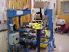
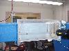
| Experimental Procedure | |||||||||||||||||
| |||||||||||||||||
| Experimental Data | |||||||||||||||||
| |||||||||||||||||
| References | |||||||||||||||||
Chanson, H. Hydraulic Design of Stepped Cascades, Channels, Weirs, and Spillways. Pergamon, 1994. Vischer, Daniel L. and Hager, Willi H. ed. Energy Dissipators. A. A. Balkema / Rotterdam / Brookfield, 1995. White, Frank M. Fluid Mechanics 4th ed. McGraw-Hill, 1999 | |||||||||||||||||
| Analysis | |||||||||||||||||
| |||||||||||||||||