 | ||||||
 | ||||||
|
|
| Introduction | |||||||||||||||||||||||||||||||
A body's inherent resistance to rotational acceleration about a specific axis is called its' mass moment of inertia about that axis. Given a fixed applied torque, an object with a higher mass moment of inertia will have a lower rotational acceleration than a body with a lower moment of inertia (in accordance with the relationship T=Jα). This is the rotational equivalent to an object's mass being a measure of its inherent resistance to translational acceleration while a force is applied (in accordance with Newton's F=ma). A rigorous definition of a moment of inertia can be found at Wolfram Research's Science World. The goals of this case study are:
| |||||||||||||||||||||||||||||||
| Theory | |||||||||||||||||||||||||||||||
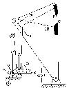
While the mass moment of inertia can, in theory, be analytically determined for any object, doing so for more than simple shapes can quickly become difficult. Most Dynamics textbooks will contain an appendix detailing the mass moment of inertia of homogeneous simple 2D and 3D shapes (e.g. Meriam and Kraige's Engineering Mechanics: Dynamics, Fourth Edition). Determining values for superpositions of simple shapes requires using the Parallel Axis Theorem: If a body with mass m has a mass moment of inertia I about its mass center, then its mass moment of inertia about a different, parallel axis (denoted J¯) a distance d from the mass center is given by the expression J¯=J+md2. The first axis must be the mass center, and the two axes must be parallel. A torsional pendulum is a device which can be used to experimentally measure mass moments of inertia for arbitrarily shaped objects. The pendulum is essentially a vertically-mounted torsional spring where the top side is fixed. The body whose mass moment is to be measured is suspended from the bottom side of the spring. The object is then rotated slightly and released so that small rotary oscillations occur. Given the period of the oscillation and a little bit of math, the mass moment of inertia can be experimentally calculated. Wolfram's Science World also has a brief explanation of the torsional pendulum. | |||||||||||||||||||||||||||||||
| Experimental Procedure | |||||||||||||||||||||||||||||||
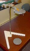
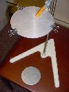
A description of the procedure for this experiment is as follows: EquipmentThis experiment will require:
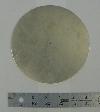
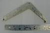
Initial SetupMeasure both the outer radius of the circular disk and the radius from its center to the attachment of the strings (they are not the same for this setup). Determine the mass of the disk. This disk will serve as the lower platform for the torsional pendulum. The pendulum should be placed on the flat table surface. The upper disk should be checked to be sure it is level. The suspended circular platform should then be checked for levelness. If it is not level while at rest, the lengths of the three strings should be adjusted until the lower platform is level. The pendulum is now ready for use. Procedure for Determining Moment of Inertia for the DiskThe lower platform should be started into small rotational oscillation. It is important that the oscillations be small, and that translational motion of the platform be minimized as much as possible; this is necessary to obtain good results. Using the stopwatch, measure the time necessary for the the platform to complete twenty oscillatory periods. Repeat ten times. The large number of samples is important to obtain a good measure of the mean oscillation period. Procedure for Determining Moment of Inertia for Concave LinkageDetermine the mass of the complex, concave link. It is important that the concave link be placed so that its mass center lies at the center of the lower circular platform. Since the link is irregularly shaped it is hard to find its centroid by eye. One way to determine the mass center is to balance the link on some sort of raised edge. Mark the line along which the edge balances. Then balance the link in a different orientation. Mark the second line along which the link balances. The mass center of the link will lie at the intersection of these two lines. Note that for this concave link the mass center does not physically lie on the link itself; it lies inside the concavity. To the left is a picture of the link being balanced. Place the link with its centroid at the center of the lower platform to ensure that their centroid axes coincide. As before, start the torsional pendulum so that it oscillates in a small, rotary motion. Using the stopwatch, measure the time for the platform and link to complete twenty torsional periods. Repeat ten times. Place the link with its centroid at the center of the lower platform to ensure that their centroid axes coincide. As before, start the torsional pendulum so that it oscillates in a small, rotary motion. Using the stopwatch, measure the time for the platform and link to complete twenty torsional periods. Repeat ten times.
| |||||||||||||||||||||||||||||||
| Experimental Data | |||||||||||||||||||||||||||||||
Geometry and Mass Information
Oscillation Time DataTimes (in seconds) for the circular lower platform to complete twenty torsional oscillations:
Times (in seconds) for the circular lower platform and the concave link to complete twenty torsional oscillations:
| |||||||||||||||||||||||||||||||
| References | |||||||||||||||||||||||||||||||
References used in creating this case study:
Thanks to Professor Sommer for his help in putting together this case study, and for access to his previous assignments regarding this experiment. | |||||||||||||||||||||||||||||||
| Analysis | |||||||||||||||||||||||||||||||
Calculations for the Moment of Inertia for the DiskThe time necessary for one oscillation of the circular disk should be calculated for each of the ten sampling periods. Calculate the mean and standard deviation of a single oscillation period. Once this is found, the experimental mass moment of inertia of the circular lower platform can be found from: J=
where
Determine the analytical mass moment of inertia for the disk about its center based on its mass and its outer radius. The formula is readily available in most dynamics textbooks. Calculations for the Moment of Inertia for the Concave LinkThe calculations for determining the mass moment of inertia for the complex, concave link are similar to the ones for finding the value for the circular disk alone. Two changes are necessary. The first is that now J=Jplatform+Jlink since mass moments obey superposition principles. Use the experimental Jlink found above for this expression. The second is that the mass m in the earlier equation is now m=mplatform+mlink since both bodies are undergoing rotation. Statistical Analysis
| |||||||||||||||||||||||||||||||