 | ||||||
 | ||||||
|
|
| Introduction | |||||||||||||||||||||
One of the least glorious but most important aspects of mechanical design is that of fastener selection. You cannot make your earth shatteringly fantastic product if you cannot put the pieces together. The use of bolts and screws as fasteners seems so commonplace as to be uninteresting, but many times the failure of such a fastener is the cause for the failure of a product as a whole. The goals of this case study are:
| |||||||||||||||||||||
| Theory | |||||||||||||||||||||
Bolts come in various shapes and strengths. The Unified National Series (UNS) specifications mandate the standards for English-system bolts and screws. A similar ISO standard covers the SI side of things. Nearly every mechanical design book has a slew of information about bolt and thread geometry and characteristics. Three particular pieces of information are of interest for this case study, which is concerned with the strength of bolts under tensile load. The first is the tensile area, At, of the bolt. The threaded portion of a bolt can be characterized by two sizes, the major and pitch diameters. The major diameter is the diameter measured between the outermost part of the threads. The pitch diameter is the diameter measured approximately halfway through the threads threads. A bolt subjected to a tensile load behaves as if its cross-section has a diameter of effectively the average of the major and pitch diameters. The tensile area is the cross-sectional area calculated using this value. eFunda.com (Engineering Fundamentals) has a nice chart of these values for UNS Coarse series bolts. This tensile should be used for stress determination. The second is the grade of the bolt. Different bolt grades are made from different materials with different heat treatments, and, accordingly, they have different strengths. The Society of Automotive Engineers (SAE) has the most commonly used grading system for UNS steel bolts. Different grade bolts have different head markings on them to allow for easier sorting/identification of a bolt's estimated strength. Unified Engineering Incorporated has a good chart of hex head bolt markings, which grades they correspond to, and also their ultimate tensile strengths. Another notable measure of a bolt's strength is its proof strength which Norton defines as the strength at which the bolt begins to take a permanent set and which is close to but lower than the yield strength of the bolt material. Norton recommends that maximum preload be 90% and 75% of a bolt's for statically- and dynamically-loaded assemblies, respectively. Both Norton and Shigley tabulate proof strengths for various bolt grades. The third is the torque necessary to produce a specified tensile load in a bolt. Shigley and Mischke develop an expression relating preload torque T to preload force F via the bolt's nominal diameter d and a quantity called a torque coefficient K, which is related to the frictional aspects of the contact between the bolt and the material surrounding it. The expression relating these quantities is T=KFd where K can be looked up in the table below which Shigley provides.
In this case study, a quick and dirty determination of the ultimate strength of a particular grade of 1/4-20 x 3/4 UNS coarse bolts is examined. Both Shigley and Norton go into much more detail on bolt loading, and the student is encouraged to review some of their material to make up for gaps in this (very) brief introduction. | |||||||||||||||||||||
| Experimental Procedure | |||||||||||||||||||||
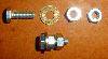
A description of the procedure for this experiment is as follows: EquipmentThis experiment will require:
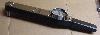
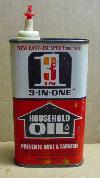
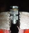
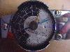
Procedure for Breaking the BoltsAssemble the bolts, washers, and nuts as shown above in the equipment list. Use a two new nuts and a new washer for each bolt. Put some of the lubricating oil along the threads and between the bolt head and the washer (a little goes a long way). Place the bolts, one by one, in the vise as shown to the right. Ensure that there's a small gap between the washer and the vise, and also that there's a small gap between the nuts. The flats of both nuts should be flush against the vise jaw faces. Use the torque wrench to break the heads off the 20 bolts and record the maximum torque required. An MPEG video of breaking one of the bolts can be viewed. An audible clank usually accompanies the bolt failure. The maximum torque recorded for one of the bolts is shown to the left.
| |||||||||||||||||||||
| Experimental Data | |||||||||||||||||||||
Bolt Failure DataMaximum torque at failure for twenty bolts in foot-pounds:
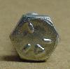
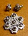
A representative sample of the mode of failure for the bolts is shown to the left. | |||||||||||||||||||||
| References | |||||||||||||||||||||
References used in creating this case study:
Thanks to Professor Sommer for his help in putting together this case study, and for access to his previous assignments regarding this experiment. | |||||||||||||||||||||
| Analysis | |||||||||||||||||||||
| |||||||||||||||||||||