Gambit - Generation of Grid for a 2-D Curved Duct
Introduction and Instructions:
In this module is a procedure that enables students to generate a structured (rectangular) grid, which will be used to solve for flow through a curved two-dimensional duct (bend) with the CFD program, Fluent. Readers should already be familiar with the notation used in this module, as described in the learning module, Fluent and Gambit - Introduction and General Information.
- We will model flow into a 90-degree circular bend in a two-dimensional duct. The boundaries of the computational domain will be formed by two circular arcs and two straight line segments as sketched below (not to scale):
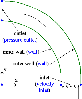
- In the sketch, the origin is the center of curvature of the duct, x is toward the right, and y is up.
- All lengths in Gambit are meters by default. The radius of the inner wall is 0.4 m, and that of the outer wall is 0.5 m.
- The blue dots on the above sketch indicate points (called vertices in Gambit) which will be used to construct the computational domain.
Log on and launch Gambit:
- Log on to any UNIX machine which has a valid license for the Fluent family of software.
- Create a Unix shell (window): From the small window in the upper left of the screen called the "Toolchest", Desktop-Open Unix shell.
- From an SGI cluster machine, enter " set path=(/usr/local/bin /disk03/local/Fluent.Inc/bin $path)" to give you access to the Fluent family of programs. The path for other systems may be different - check with the system administrator for the proper path. Note: This line should be added to your .cshrc file so that you won't have to add it manually every time you log in.
- At this point, if not already done previously, you should create a new directory called Fluent, so that all of your Fluent projects reside on this directory. To do so, Enter "mkdir Fluent" and then go to this new directory by entering "cd Fluent".
- Also create a new directory called Gambit, as a subdirectory of Fluent. Go to the Gambit subdirectory by typing "cd Gambit".
- Gambit may now be launched. Enter "gambit -id curve &". After a while (sometimes a couple minutes!), the main Gambit window should appear on your screen. Note the "&" at the end of the command, which tells UNIX to run this in background mode. This will free up your UNIX shell for other commands while Gambit continues to run.
- In Gambit, when the mouse cursor is placed over a button, a short description of the function of that button appears in the lower right window under Description. This is useful in implementing the commands given below.
- Gambit needs to know for which code it is generating the grid. At the top of the screen, Solver-Fluent 5.
Create some data points (vertices) for the desired geometry:
- Create a vertex on the inner wall at the inlet of the duct. In Geometry, Vertex Command Button-R-Create Vertex-From Coordinates. In Create Real Vertex-Global, enter 0.4, 0, and 0 for x, y, and z coordinates respectively. Apply. A vertex is created, as indicated by a small plus sign at this location.
- Create another vertex on the inner wall at the duct outlet, with coordinates (0,0.4,0). Apply to actually create and draw the vertex.
- In similar fashion, create the rest of the vertices defining the outer duct wall, i.e. (0,0.5,0) and (0.5,0,0). Gambit will label these vertices for you by default.
- Finally, create a vertex at (0,0,0). This vertex is at the origin, i.e. at the center of curvature for both of the walls.
- At this point, it is wise to zoom in somewhat to see the vertices more clearly. There are two ways to do this. You can zoom in and move with the right mouse and middle mouse, respectively. Or, to fit all the geometry into the available screen space (a very handy tool!), in Graphics/Windows Control (near the bottom right), Fit to Window.
- In the main Gambit window near the upper left, File-Save. This will save your work so far. It is a good idea to do this every so often, especially after a major task is completed.
Create edges from these vertices to define the computational domain:
- Now some edges will be created to define the inlet, the outlet, and the two circular arcs. Under Geometry, Edge Command Button. (Note: If the button is already open, clicking it again will make the options disappear! If this happens, click it again.)
- Under Edge, R-Create Edge-Straight. A new window called Create Straight Edge will appear.
- In Create Straight Edge, make sure the text area called Vertices is highlighted - if not, click in that area. Vertices are selected by Shift + left mouse click. Select the two vertices which define the inlet to the duct (lower right).
- Type in an appropriate label for the edge about to be created. I suggest "inlet" or something equally descriptive. Apply. Gambit will create a straight edge between these two vertices. A yellow line should be drawn on the screen connecting the vertices.
- In similar fashion, create another edge for the outlet (top left). Name this edge "outlet". Don't forget to Apply.
- Now Close the Create Straight Edge window.
- Next, the large circular arc (outer wall) will be created. Under Edge, R-Create Edge-Arc. A new window called Create Real Circular Arc will appear.
- There are two methods for creating a circular arc. The first one (default) requires selection of a center vertex and two end vertices. This is the one we want. (The second method requires selection of three vertices along the arc.)
- Select the vertex at the origin as the Center vertex. Click in the text box called End-Points, and select the two vertices along the outer wall, which will form the circular arc. Type in a label like "outer wall" and Apply. A yellow circular arc should appear.
- Repeat for the inner wall, and call it "inner wall". Don't forget to Apply.
- In the main Gambit window near the upper left, File-Save. This will save your work so far. It is a good idea to do this every so often, especially after a major task is completed.
Generate a face from the available edges:
- Under Geometry, Face Command Button-R-Create Face-Wireframe.
- It is important to select the edges in order when creating a face from existing edges. (I like to select them in mathematically positive counterclockwise order). Select the inner circular arc, then the inlet straight line, the outer circular arc, and finally the outlet straight line. These edges outline the "wireframe" of a closed face.
- In Create Face From Wireframe, type in a label for this face if desired ("domain" is suggested), and Apply. If all went well, a blue outline of the face should appear on the screen; this is a face, which is now ready to be meshed.
Define node points along the edges:
- In Operation, Mesh Command Button-Edge Command Button. Mesh Edges should be the default window that opens; if not, Mesh Edges.
- Select the inlet, and in Mesh Edges, change the Spacing option from Interval Size to Interval Count. Enter the number 20 as the Interval Count.
- It is desirable to cluster or bunch nodes close to the walls. This is accomplished by changing Ratio (in the Grading section of the Mesh Edges window). Turn on double sided so that bunching is done on both walls. A ratio of 1.1 is recommended for both ends of the edge (Ratio 1 and Ratio 2) so that there are lots of nodes near both walls, and not so many nodes near the center. (This helps to resolve the boundary layers along the walls.) Apply. Blue circles should appear at each created node point along that edge.
- Note that at any time, if you make a mistake, you can undo your previous command by clicking on the Undo button, which looks like a looped arrow.
- Next, select the outlet edge. The same node distribution as created for the previous edge is also desired here, so nothing needs to be changed. Simply Apply; otherwise the node distribution will not be saved.
- Similarly, define 50 node points along each circular arc, with no bunching (set both Ratio 1 and Ratio 2 to 1.00). Don't forget to Apply each time.
- When all edges have been assigned nodes, save your work, and Close the Mesh Edges window.
Specify the boundary types on all edges:
- In order for the mesh to be properly transferred to Fluent, the edges must be assigned boundary types, such as wall, inlet, outlet, etc. Actual numerical values, such as the outlet pressure and inlet velocity, will be specified as boundary conditions from within Fluent itself. In Operation, Zones Command Button-Specify Boundary Types Command Button.
- In the Specify Boundary Types window, change Entity to Edges (the default is usually Faces). In this problem, which is 2-D, boundary conditions will be applied to edges rather than to faces.
- Select the inner wall, which will become a wall. The default Type should be Wall. If not, change it to Wall, and type in some name like "inner wall". Apply. Some words indicating this boundary condition will appear on the screen.
- Repeat for the outer wall, calling it "outer wall". Note that these must be defined separately, even though they are both walls. Be sure to Apply, or the boundary condition will not actually be assigned.
- Select the inlet. In similar fashion, make this a Velocity Inlet boundary condition named "inlet". Be sure to Apply.
- Finally, Select the edge defining the outlet. Name this boundary type "outlet", and change Type to Pressure Outlet. Apply.
- Now Close the Specify Boundary Types window.
Generate the mesh on the face:
- Under Operation, Mesh Command Button-Face Command Button. The default window that pops up should be Mesh Faces. If not, Mesh Faces.
- Select the face by shift clicking on one of its edges. Change Elements to Quad if necessary, for rectangular (structured) elements. Also change Type to Map if necessary. The Spacing options will be ignored since nodes have already been defined on all edges of this face.
- Generate the mesh by Apply. If all goes well, a mesh should appear after some calculation time. Zoom in to see how the cells are nicely clustered near the inner and outer walls of the duct. This will help Fluent to more accurately resolve the flow near these walls.
- Zoom back out so that the entire mesh can be clearly seen. This is most easily accomplished by clicking on Fit to Window in the Graphics/Windows Control (near the bottom right of the screen).
- You can now Close the Mesh Faces window.
Write out the mesh in the format used by Fluent, and then exit Gambit:
- In the main Gambit window, File-Export-Mesh-Accept. (The default file name can be changed here if desired, but the default name is acceptable in this case.)
- The Transcript (at lower left) informs you when the mesh is written correctly to the file. If there is an error here, you must have done something incorrectly. You may need to re-do the mesh or the boundary conditions.
- Exit Gambit: File-Exit-Yes.
- When Gambit exits, the UNIX window will re-appear. Enter "ls -la" to see the files created by Gambit. The curve.msh file is the one to be used by Fluent.
- It is a good idea to move this file into the Fluent directory, so that it is ready to be read in. Enter "cd ..", which will move your working directory up one level to the Fluent directory. To verify, Enter "pwd" (print working directory).
- Now enter "mv Gambit/curve.msh curve.msh", which will move the file from the Gambit subdirectory into the working directory. Enter "ls -la" to verify that the file is now in the Fluent directory.
- The mesh file should now be ready for use by Fluent. You may move on to the next learning module, Fluent - Particle Trajectories in a Curved Duct, which describes how to run this case with the CFD solver, Fluent.