 | |||||
 | |||||
|
|
| Introduction | |
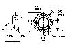
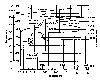
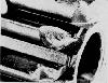
A case history in failure analysis told from the viewpoint of a consultant. Late in March 1968, I was consulted about a series of failures in the pinions in automotive starter motor drives. In this particular case, a number of pinions had failed sufficiently prematurely to cause the company considerable expenditure through warranty replacements (cost of about $50 for each replacement, including new pinion, mechanic's time, paper work, etc., not to mention customer good will some pinions were failing after a few weeks use). The pinion in question is shown in Exhibit A-1. This pinion was used to drive a large gear in a starter motor, with intermittent loading being applied rather rapidly, to the extent of being essentially impact loading on some occasions. The material specified was AISI 8620 steel, for which the Time-Temperature-Transformation (TTT) diagram is shown in Exhibit A-2. This same pinion had been used extensively in previous applications with very little difficulty. Its use in somewhat different circumstances (in conjunction with a more powerful engine) caused an unacceptably large number of failures. | |
| Experimental Data | |
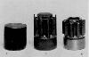
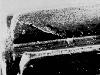
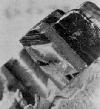
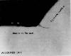
Material was received as cold-drawn bars about 20 ft. long with a diameter of 1.000 in. (+ 0.000, - 0.002) with a maximum surface seam of 0.010 in. The bar was sheared to slugs of 1 in. length, as shown in Exhibit A-3a. The slugs were normalized at 1310 degrees F in a continuous belt furnace. Belt speed was 4.1 ft./hr. with a total cycle of 10 hours. Specifications permitted a maximum hardness of Rockwell 80 B. Slugs were phosphate coated followed by application of a soap lubricant. A cold heading and finish extrusion on a heavy press produced the shaped teeth shown in Exhibit A-3b. A series of machining operations drilled a center hole, rough finished the hub, and finished the rest of the pinion to final dimensions. All surfaces were copper plated to a minimum thickness of 0.00035 in. and a maximum of 0.001 in. The copper plate was turned off the hub outside diameter. This was followed by processing in a continuous-belt carburizing furnace. The pinions had a total heat cycle of 7.5 hours with a furnace temperature of 1650°F and a gas atmosphere. Specifications call for a total case depth of 0.035 - 0.045 in. and a minimum surface carbon content of 1.00 percent. The copper plate is stripped in preperation for a second carburizing operation. This is similar to the first but with a furnace temperature of 1560 degrees F. Baskets of pinions move automatically through the furnace into a quench tank (molten salt at 425 degrees F or oil at 130 degrees F) followed by a spray wash. The case depth on the hub (before grinding)should be 0.045 - 0.055 in. The tooth case (at pitch diameter)should be 0.018 - 0.024 in The quenched pinions are tempered by passing through a furnace at 350 degrees F at a belt speed of 1.2 in./min. for 2 hours at heat followed by air cooling. Specifications require a Rockwell hardness of 79-82 A on the teeth. Tooth structure should have tempered martensite on the case with a maximum of 10% retained austenite and a combination of martensite and fine pearlite in the core. Grinding operations on the hub and on the inside diameter produce the finished pinion shown in Exhibit A-3c. A number of new, unused pinions were examined visually with a magnifying glass and at 20X. The drive side surface ( Exhibit A-1) of many teeth had long "stringy" defects and general roughness to an even greater extent than that shown along the top of the tooth in Exhibit A-4. The tooth in Exhibit A-4 shows an extreme example of a surface imperfection on a tooth of an unused gear. This defect extended across the root surface and up the back side of the neighboring tooth. Two small chips were removed from the defect in the root surface. Magnetic particle inspection of this pinion indicated the presence of sub-surface cracks along the pitch line and at the root of the teeth. Examination of a number of failed pinions revealed each had one or more teeth with similar failures, A typical one is shown in Exhibit A-5. This tooth was one of three on this pinion which apparently failed in the same manner. The second failed tooth appears in the lower part of Exhibit A-5 The third tooth is below the second one in the orientation shown. Exhibit A-6 shows the same fractured tooth from the top. Obviously, the company was anxious to obtain a technical solution to a costly technical problem. In discussing the problem with the company's representative, I sensed that there was also a matter of a strong difference of opinion as to the source of the trouble (and therefore of responsibility) between two (or possibly more) operating groups within the company. My report might accordingly function as that of a referee. The choice of AISI 8620 is entirely reasonable since it is quite possible to develop structures which will meet the stated specifications. It is true that a number of other steels can meet the specifications equally well, but AISI 8620 is less expensive than most of the others. Spectrographic analysis confirmed the material was AISI 8620. The normalizing operation specified a furnace temperature of 1310 Degrees F. Examination of Exhibit A-2 indicates that this temperature is marginal. A metal temperature of 1325 to 1330 degrees F would appear to be better for ensuring proper structure before cold-forming the teeth. (There was no evidence, however, of specific difficulty or failure originating from this marginal temperature.) While the appearance of the tooth surface in Exhibit A-4 is an extreme example, the general roughness was found on many of the pinions examined, both new and used. This appearance is not typical of surfaces which have been cold worked and could be due to small surface seams in the original stock, dirty dies used in forming the teeth, and/or stripping the copper plate. The dimensional tolerances shown in Exhibit A-1 seem reasonable. One critical dimension is not clearly stated. Ob- serve the situation at the end of the tooth at the base of the surface, which is at an angle of 40 degrees to the end of the pinion. It is not obvious that a fillet radius is stated, although one could infer that it should be 0.01 to 0.02 in., i.e., the same as the fillet radius at the base of the pinion teeth. The failed teeth shown in Exhibits A-5 and A-6 were typical of the failures on other pinions. These are characteristic fatigue failures. Failure was initiated in the fillet at the root of the machined surface, which is at 40 degrees to the end of the pinion. There is a "smooth" portion adjoining this fillet which merges into a "rough" portion of the fracture at some distance from the fillet. Exhibit B-1 is a section of this failure at the fillet. This is at the location for which the radius is not clearly specified (see comment on Exhibit A-1 above). If we assume that this radius should be the same as at the root of the teeth (0.010 to 0.020 in.), it is obvious that the assumption is not justified in this case, since the radius is approximately 0.002 in. Micrographic examination of the drive (pressure) side of the failed tooth (near the fracture) showed reformed martensite. The presence of martensite indicated high localized stress. A Rockwell hardness of 80 A (equivalent to Rockwell 58 C) was measured on the hub. A diamond pyramid hardness of 730 (equivalent to Rockwell 61.50) was found at 0.003 in. below the surface at the pitch line. This is just slightly above specification limits. Tooth core structure is tempered (low-carbon) martensite. The tooth case shows approximately 3040 percent retained austenite to a depth of 0.006 in. This obviously exceeds the specification limit of 10 percent. | |
| Conclusion | |
The major factor leading to tooth failure was the high concentration of stress at the root of the surface at 40 degrees to the end Of the pinion. This has several contributory factors: stress concentration from the much-too-small fillet radius; increase in applied load above previous requirement; and probable existence of sub-surface cracks before use The general appearance of new pinions and failure to meet various specifications are, in this case, of secondary consideration, although these, in the absence of the primary factor of high stress concentration, would lead to excessive wear and pitting along the wear surfaces. This in turn could result in fracture. These secondary aspects are difficult to reconcile with high-quality work in which there has been proper control of processing and proper inspection. Aftermath — Further CommentsWhen the company's representative received the report and Discussed it with me, his major comment was, "How could we have missed that?" I had no answer to that, since fatigue failures initiating at a stress concentration, such as this failure, are all too common. In February 1969, I checked with the company representative to see what developments, if any, had come from the investigation. He made it clear that there was no question about the technical solution. Despite this, however, no change had been made in the pinion (tooling costs, etc., associated with even a small design change are costly). Even so, the warranty problem had receded to an acceptable level by using the report as a form of pressure on the production people to "sharpen up." Proper design changes could be made later, at retooling time for new models, if needed. | |
| References | |
This case history was reported by Charles O. Smith, Professor of Engineering, Rose-Hulman Institute of Technology, and appeared in Engineering Education, November 1983 This material was adapted from ECL 135 at Carleton University See also the Brief Notes on Failure analysis | |