Introduction

Internal combustion engines are very common in our daily lives. Today they range from the cars that most of us drive to the lawn mower that we use to mow the lawn. These engines consume bout 30% of the U.S. energy budget, which is about 20% of the world's 
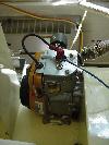
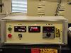
energy budget. The IC engine that is used in this particular experiment is a four stroke, 1 cylinder engine, with a displacement volume of 77.6ml. The intake and Exhaust valves are placed on the side of the cylinder, in a side or flat-head configuration. When air and fuel or gas goes into an IC engine, the output products are; power, exhaust, and heat.

Yet, the output power differs from the power developed by the gas mixture in the cylinder. This power is called the indicated power. In order to get the indicated power, one needs to find the work done per unit time. And to obtain the work done, the pressure and the gas volume 
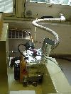
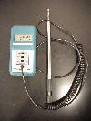
at each instant need to be determined. To measure the exhaust composition, gas detector tubes are used. The heat can be determined by measuring the flow of cooling air and its 
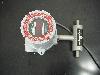
temperature rise. Power can be calculated using the speed and torque. In this whole experiment, four different speeds were used to obtain different sets of results.

Experimental Procedure

Air Mass Flow Calculation

  • Make a data sheet that consists of the following; date, time (start/end), speed, temperature, pressure, humidity, torque, velocity, and mass flow.
  • Turn engine on to a speed of 1200rpm and give it time to warm-up.
  • Using a thermal mass flow meter placed upstream of a damping box, measure the inlet air flow into the engine.
  • Using a hot-wire anemometer, measure the temperature and the velocity at the inlet with the thermal mass flow meter still attached to the damping box.
  • You should be able to read off all the values for the list on the data sheet from the hot-wire anemometer, thermal mass flow meter, and the anemometer that is attached to the engine itself.
  • Run the engine at three other different speeds (1500, 1800, and 2000) and perform the same exact procedures as before and record all data.
  • Using the collected data, you should be able to calculate the M-dot Anemometer or Anemometer mass-flow, and the M-dot flow or Thermal mass-flow.
  • In order to calculate the anemometer mass flow, or the M-dot anemometer, you need to calculate the change in velocity (V-dot), the entrance area, and the density.
  • To calculate the change in velocity (V-dot), use the following formula; (8/3)*(Average of all the velocities(m/s))*((PI)*((Diameter(in)*0.0254(m/in))^2)/4)))
  • To calculate the density use this formula; Rho(Kg/m^3)=(PressureKPa)/((0.287(KJ/Kg*K))*(Average Temperature +273.15)(K))
  • In order to calculate the thermal mass-flow, or the M-dot of mass-flow, use the following formula; (Average of the mass flow(g/min))/(60(s/min)*1000(g/Kg))
Experimental Data
Download Files
FileTitleTypeSize
DATA2.xlsResults Microsoft Excel 18K
Analysis
  • Calculate Air Mass-flow.